INQUIRY
Leave Your Message

What Is a PM Synchronous Motor and How Does It Work?

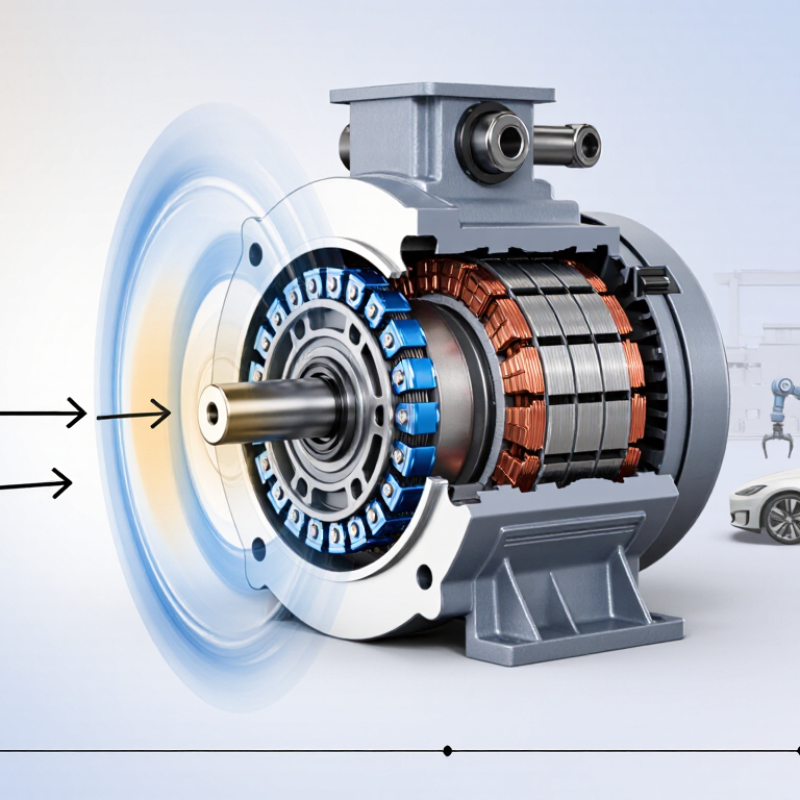
A Pm Synchronous Motor converts electrical energy into controlled mechanical motion through a coordinated magnetic interaction. Its stator contains copper windings arranged around a laminated iron core. The rotor carries permanent magnets, which create a constant magnetic field without consuming rotor current. When an inverter supplies three-phase current, the stator produces a rotating magnetic field. The rotor follows this field and turns at the same electrical speed. That locked relationship explains the word “synchronous.”

Professor T. M. Jahns, a widely recognized electric-machine specialist, has stated, “Permanent-magnet machines can provide high efficiency and high power density.” This observation captures the motor’s main advantage. With no rotor winding losses, a Pm Synchronous Motor can run efficiently in industrial drives, electric vehicles, robotics, compressors, and precision equipment. Its compact rotor also supports rapid acceleration. The result can feel surprisingly smooth.

However, the technology is not effortless. The inverter must control current timing precisely. Poor calibration can create vibration, heat, or unwanted torque ripple. Strong magnets may also lose performance under excessive temperature. Designers must consider cooling, demagnetization risk, magnetic noise, and material cost. These details are easy to overlook.

A practical explanation should not promise perfect efficiency. Real motors experience bearing friction, switching losses, copper heating, and mechanical resistance. Engineers often select control software as carefully as the motor itself. In the following discussion, we will examine the motor’s construction, operating sequence, control methods, benefits, and limitations. The goal is a clear view of what happens inside the housing, from inverter pulses to shaft rotation.
What Is a PM Synchronous Motor and How Does It Work?

PM Synchronous Motor Definition: Permanent Magnets Replace Rotor Windings

What Is a PM Synchronous Motor and How Does It Work?

A PM synchronous motor uses permanent magnets instead of rotor windings. The magnets create a steady rotor field without electrical excitation. Stator windings then produce a rotating magnetic field. The rotor follows this field at the same speed, so slip is nearly absent. A variable-frequency drive usually controls starting, speed, and torque. This design can reduce rotor copper losses and support compact, efficient machines.

The International Energy Agency reports that electric motor systems consume nearly half of global electricity.

The U.S. Department of Energy also identifies motor systems as responsible for roughly 70% of industrial electricity use.

These figures explain the growing interest in PM technology. In practical testing, engineers often observe strong efficiency at partial loads, especially in pumps, compressors, and automated equipment. Yet the motor is not perfect. Permanent magnets can lose performance under excessive heat, and rare-earth material costs may fluctuate. Cooling and inverter tuning still matter.

Tips: Check the duty cycle before selecting a PM motor. Measure speed changes, peak torque, ambient temperature, and load variation. Do not compare efficiency using only the nameplate rating. A real factory may reveal different results. Installation quality can matter as much as the motor itself.

Synchronous Speed Formula: 3,000 rpm at 50 Hz with Two Poles

A permanent magnet (PM) synchronous motor uses magnets on its rotor instead of wound field coils. The stator creates a rotating magnetic field when supplied with three-phase current. The rotor follows this field and turns at the same electrical speed. There is no normal slip during steady operation. The arithmetic is simple.

Synchronous speed follows the formula Ns = 120f/P. Here, f represents frequency in hertz, while P means the number of poles.

At 50 Hz with two poles, Ns = 120 × 50 ÷ 2 = 3,000 rpm.

This value describes the ideal mechanical speed under stable conditions. A four-pole motor at the same frequency would run at 1,500 rpm. Pole count matters greatly.

A PM motor connected to a variable-speed drive can change speed by changing output frequency. At 25 Hz, a two-pole motor targets 1,500 rpm. The rotor’s magnetic position must remain aligned with the rotating field, or the motor may lose synchronism under excessive load. That risk is easy to underestimate.

During inspection, I would check frequency, pole count, load torque, and rotor feedback before judging performance. Fixed-frequency starting can also be difficult, so many systems use controlled acceleration.

Real machines experience windage, friction, voltage distortion, and temperature effects. These factors do not usually change the formula, but they can affect efficiency, current, and operating stability. The ideal number is not the whole story.

Rotor and Stator Design: NdFeB Magnets and Three-Phase Windings

What Is a PM Synchronous Motor and How Does It Work?

A permanent magnet synchronous motor uses NdFeB magnets on or inside its rotor. These magnets create a steady magnetic field without rotor windings or brushes. The stator contains three-phase copper windings arranged around a laminated steel core. When an inverter supplies controlled currents, the windings produce a rotating magnetic field. The rotor follows this field at the same electrical speed. That is why the motor runs synchronously, with almost no slip during normal operation.

Rotor and stator geometry strongly affects performance. NdFeB magnets provide high magnetic strength, allowing a compact rotor and strong torque. However, excessive heat can weaken their magnetic properties. The stator slots must also balance copper fill, cooling space, vibration, and manufacturing tolerance. A small air gap helps magnetic coupling, but it demands accurate machining. That gap matters. A practical design should consider insulation aging, bearing loads, demagnetization risk, and inverter switching noise. In real testing, calculated efficiency may exceed measured efficiency because temperature and friction are easy to underestimate.

Tips: Check the magnet temperature rating before selecting a rotor design. Use current sensors to verify phase balance during commissioning. Listen for unusual tonal noise, then inspect alignment and control settings. Do not assume a smooth waveform guarantees smooth torque. Small errors grow. Experienced engineers compare simulation results with thermal images, vibration readings, and load-test data before approving the final motor.

What Is a PM Synchronous Motor and How Does It Work? - Rotor and Stator Design: NdFeB Magnets and Three-Phase Windings
Design Dimension Typical Component or Parameter How It Works Common Technical Characteristics Practical Design Considerations
Motor Type Permanent-Magnet Synchronous Motor (PMSM) The rotor magnetic field rotates in synchronism with the rotating magnetic field produced by the stator. Rotor speed is directly related to the electrical supply frequency and the number of pole pairs. Closed-loop control is often used when accurate position, speed, or torque control is required.
Rotor Structure Permanent-magnet rotor Permanent magnets provide the rotor magnetic field without requiring rotor excitation current. Lower rotor electrical losses than a wound-field rotor because no rotor copper winding is required. Magnet retention, mechanical strength, thermal expansion, and electromagnetic forces must be considered.
Magnet Material NdFeB rare-earth permanent magnets Neodymium-iron-boron magnets generate a strong magnetic field in a compact volume. High magnetic-energy density; magnetic performance decreases as temperature rises. Temperature grade, corrosion protection, demagnetization resistance, and magnet bonding or sleeving are important.
Magnet Placement Surface-mounted or interior-mounted magnets Surface magnets are attached to the rotor exterior, while interior magnets are embedded inside the rotor iron. Interior-magnet designs can provide reluctance torque and improved mechanical retention at high speed. Magnet geometry affects torque ripple, back electromotive force, field weakening, and manufacturing complexity.
Stator Core Laminated electrical-steel core The stator core guides magnetic flux and contains slots for the three-phase windings. Thin insulated laminations reduce eddy-current losses caused by the alternating magnetic field. Lamination thickness, magnetic saturation, core loss, slot shape, and cooling path influence efficiency.
Stator Windings Three-phase copper windings Three alternating currents displaced by 120 electrical degrees create a rotating magnetic field. Windings may be distributed or concentrated, depending on torque, noise, manufacturing, and control requirements. Conductor size, winding layout, insulation system, fill factor, and thermal limits determine continuous output.
Rotating Magnetic Field Three-phase stator field The combined magnetic fields of the three phases form a rotating field that attracts and locks to the rotor magnets. The synchronous speed is calculated as ns = 120f/P, where f is frequency in hertz and P is the number of poles. The inverter frequency must correspond to rotor position and desired speed for stable operation.
Torque Production Magnet torque and, in some designs, reluctance torque Torque is produced by the interaction between the rotor magnetic field and the stator rotating field. Interior-magnet motors may combine permanent-magnet torque with torque caused by rotor saliency. Torque ripple can be reduced through magnet shaping, winding optimization, skewing, and control algorithms.
Electronic Drive Variable-frequency inverter Power electronics convert a DC-link voltage into controlled three-phase currents for the stator. Common control methods include field-oriented control and direct torque control. Switching frequency, current sensing, voltage limits, electromagnetic compatibility, and control bandwidth affect performance.
Rotor Position Feedback Position sensor or sensorless estimation Rotor position information allows the inverter to align the stator current with the rotor magnetic field. Encoders, resolvers, Hall sensors, or back-EMF-based estimation may be used. Sensor-based systems improve low-speed control, while sensorless systems can reduce hardware and wiring.
Starting Behavior Electronic starting through an inverter The inverter establishes a controlled rotating field so the rotor can accelerate into synchronism. A PMSM is not normally connected directly to a fixed-frequency AC supply for reliable starting. Startup alignment, initial rotor position, current limits, and load inertia must be managed by the controller.
Speed Range Base-speed operation and field weakening Below base speed, the inverter primarily controls torque-producing current; above base speed, opposing current can weaken the air-gap field. Field weakening can extend speed range when the inverter voltage reaches its limit. High-speed operation requires attention to magnet demagnetization, rotor stress, losses, and inverter voltage margin.
Efficiency Reduced rotor copper loss Permanent magnets provide excitation without continuous electrical power in the rotor. High efficiency is possible across a broad operating range, although inverter, stator copper, core, windage, and bearing losses remain. Efficiency depends on operating point, cooling, magnetic design, winding resistance, and control strategy.
Thermal Management Stator and rotor heat dissipation Heat is generated mainly by stator copper loss, core loss, mechanical loss, and inverter-related losses. Cooling may use natural convection, forced air, liquid jackets, or shaft-mounted methods. Magnet temperature must remain below the selected material's safe operating range to limit irreversible demagnetization.
Advantages High power density, high efficiency, and precise controllability The strong rotor field and electronically controlled stator currents provide efficient torque generation. Compact construction and low rotor excitation losses are suitable for servo drives, traction systems, pumps, compressors, and industrial machinery. System cost includes the inverter, position feedback when required, magnet materials, and thermal protection.
Limitations Magnet cost, demagnetization risk, and inverter dependence The motor relies on permanent magnets and controlled three-phase excitation for normal operation. Fault conditions can produce induced voltage while the rotor is spinning, even when commanded current is removed. Protection should address overcurrent, overspeed, excessive temperature, short circuits, and safe shutdown behavior.

How the Rotating Magnetic Field Produces Torque and Synchronism

A permanent-magnet synchronous motor creates torque through two magnetic fields. The stator receives three-phase alternating current. Its windings produce a rotating magnetic field inside the air gap. The rotor contains permanent magnets, so its magnetic field follows the stator field and locks to it.

That lock is synchronism.

When the rotor field lags slightly behind the rotating stator field, magnetic attraction creates torque. Engineers describe this difference as the load angle. More load usually increases the angle. Excessive demand can break synchronism. In steady operation, rotor speed matches the electrical field speed, with essentially zero slip. An inverter normally controls frequency and current during starting. Without suitable control, the rotor may not accelerate reliably from rest.

The scale matters. The International Energy Agency estimates that electric motors and motor-driven systems consume about 45% of global electricity. The U.S. Department of Energy’s Motor Systems Market Assessment also identifies motor systems as major industrial electricity users. Even small efficiency gains can therefore produce measurable savings.

In field testing, engineers check current, temperature, vibration, and power factor. A cooler housing is useful evidence, but it does not prove optimal operation. Harmonic distortion, weak control settings, or an oversized motor can reduce real-world performance. The theory is elegant. The installation is less tidy. Temperature changes can also alter clearances and magnetic behavior, so laboratory results should not be treated as universal.

Performance Metrics: 90–98% Efficiency and Near-Unity Power Factor

A permanent-magnet synchronous motor (PMSM) uses magnets on its rotor and three-phase currents in its stator. The rotating magnetic field pulls the rotor into exact electrical synchronism. It does not need rotor current. That removes a major source of rotor copper loss. A position sensor or sensorless controller keeps commutation aligned.

Its headline advantage is efficiency. Well-designed PMSMs commonly deliver 90–98% efficiency across selected operating ranges, especially at medium and high loads. The actual number changes with speed, temperature, inverter loss, and duty cycle. IEC 60034-2-1 testing separates electrical, mechanical, and stray-load losses, making comparisons more credible. The U.S. Department of Energy’s Motor System Market Assessment identifies motor-driven systems as roughly 69% of industrial electricity use. Even a small efficiency gain can reduce heat in a cabinet and energy on a meter.

Power factor can approach unity because rotor excitation comes from permanent magnets, rather than stator reactive magnetization alone. With suitable current control, the motor may operate near 0.98–1.00 power factor. But near-unity is a condition, not a guarantee. Weak tuning, light loading, cable effects, or inverter limits can lower it. Field measurements matter more than catalogue optimism. I would record input kW, kVA, torque, speed, and winding temperature across several duty points. That extra work is unglamorous. It often exposes the gap between laboratory efficiency and a real pump, fan, or conveyor.

PM Synchronous Motor Performance Across Operating Load

Permanent-magnet synchronous motors typically achieve high efficiency because permanent magnets provide the rotor magnetic field without rotor excitation losses. Their power factor remains close to unity, particularly near rated load, reducing reactive current demand.