Choosing an Interior Permanent Magnet motor in 2026 means balancing efficiency, torque, cost, and operating conditions—not chasing one headline specification. The International Energy Agency’s Global EV Outlook 2025 reports that electric-car sales exceeded 17 million in 2024, representing more than one-fifth of global car sales. It projected sales would surpass 20 million in 2025. That growth raises the stakes for motor selection, but it does not make every motor topology right for every vehicle.
An Interior Permanent Magnet motor places permanent magnets inside its rotor. This arrangement can combine magnet torque with reluctance torque, supporting strong low-speed performance and efficient operation across a broad speed range. Yet results depend on the complete drive system. Compare efficiency maps at your actual operating points, not just peak-efficiency figures. Check inverter compatibility, cooling limits, maximum speed, noise, vibration, and magnet-temperature protection. A delivery van facing repeated stop-and-go routes may need a different balance than a high-speed passenger car.
Small details matter.
The IEA’s Global Critical Minerals Outlook 2024 also highlights supply-chain exposure for minerals used in clean-energy technologies. It does not rank motor designs, but it is a useful reminder to examine magnet sourcing, material specifications, and supplier traceability. Ask manufacturers for test conditions, durability evidence, and performance data across temperature ranges. Be cautious when claims lack comparable methods. A polished efficiency curve can still leave practical questions unanswered. In this guide, we’ll assess the criteria that help engineers and buyers choose an Interior Permanent Magnet motor suited to real workloads in 2026.
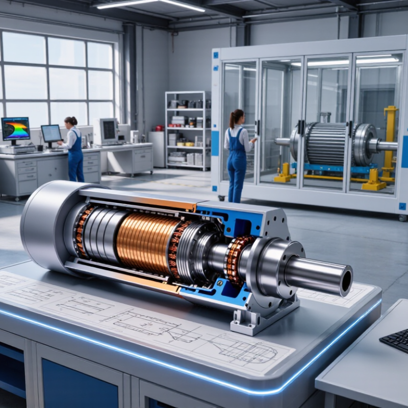
Before choosing an interior permanent magnet motor, define the work it must perform. Record the driven load, required torque, speed range, and acceleration time. A conveyor may need steady torque, while a pump can face frequent starts. Peak torque alone can mislead. Include the full operating cycle, including idle periods and reversals.
Check the available voltage, inverter limits, mounting space, shaft dimensions, and cooling method. Note ambient temperature, dust, vibration, and any washdown exposure. These details affect motor sizing and insulation choices. Specify continuous and short-term duty separately. It is easy to overlook a brief overload that happens dozens of times per shift.
Tips: Measure the real cycle, not just the nameplate load. Keep a simple log of speed, current, and temperature during representative operation. Not just peak torque. Confirm whether the application needs precise low-speed control or frequent regenerative braking. Then review the assumptions with the machine designer. Early estimates are useful, but they are rarely perfect; revise them when measured data disagrees.

Start with the torque-speed map, not a peak-power number. A V-shaped magnet layout can provide useful reluctance torque and field-weakening capability, but results depend on rotor geometry and control calibration. Other arrangements may trade high-speed performance for torque density or manufacturing simplicity. Small details matter. The IEA’s Global EV Outlook 2024 reports nearly 14 million electric car sales in 2023, around 18% of global sales. That growth makes duty-cycle matching important: a city vehicle and a high-speed commercial application need different motor maps.
Compare continuous and peak torque, base and maximum speed, efficiency across the operating range, and allowable winding and rotor temperatures. Check the inverter’s voltage and current limits alongside the motor; a strong motor can underperform when the pair is mismatched. Ask for efficiency-map test conditions, including coolant temperature and measurement method. Review magnet-retention strength, rotor stress at maximum speed, demagnetization margin, torque ripple, and noise. Not always. A tidy specification sheet may omit transient heat buildup or real-world cooling limits, so validate shortlisted designs on a representative duty cycle before choosing.
How to Choose an Interior Permanent Magnet Motor in 2026?
Choose an interior permanent magnet (IPM) motor around its real duty cycle, not its peak-efficiency figure. A pump running steadily may need a different efficiency profile from a conveyor that starts under load. Compare efficiency across the expected speed and torque range. Check continuous and peak ratings, cooling requirements, and temperature limits in the motor’s datasheet. Small details matter. A hot enclosure can reduce available output.
Tips: Confirm the drive’s voltage, current, and speed range match the motor. Check whether its control supports the required sensor type and field-weakening operation. Ask for a motor-drive compatibility review before ordering. A bench test can reveal issues that a spreadsheet may miss.
Control quality matters too. Accurate rotor-position feedback can help maintain smooth torque at low speeds, while sensorless control may suit some applications but needs validation across the operating range. Review startup behavior, braking needs, and communication requirements with the drive supplier. Do not assume an existing inverter will work simply because its power rating looks close. I would also revisit the load assumptions: real machines rarely follow a perfect duty cycle, and that gap can change the choice.
Drive compatibility: Synchronous speed is calculated as 120 × electrical frequency ÷ pole count. These values help check whether a motor’s pole count and drive frequency suit the target speed. An inverter can vary frequency to control speed; the motor’s usable range also depends on its voltage, current, thermal, and mechanical limits. This chart shows calculated synchronous speeds, not efficiency ratings.
How to Choose an Interior Permanent Magnet Motor in 2026?
Evaluate Thermal Limits, Reliability, and Maintenance Needs
Thermal limits deserve attention before comparing headline efficiency figures. Match the motor’s continuous and peak ratings to the actual duty cycle, not just the machine’s maximum load. Check winding and magnet temperature limits, cooling method, and ambient conditions. A motor in a warm enclosure may need more cooling than the same unit in open air. Heat adds up. Ask for temperature-rise data under conditions close to your application.
Reliability depends on more than the motor’s design. Review bearing life, insulation rating, vibration limits, and protection against dust or moisture. Confirm that sensors can detect rising temperatures or unusual vibration early. A neat calculation can still miss frequent starts, brief overloads, or restricted airflow. Those details matter. Consider whether bearings, seals, and cooling components are accessible without removing nearby equipment.
Tips: Compare service intervals and replacement procedures before purchase. Check whether your team can inspect the cooling passages and connections safely. Keep a simple log of operating temperature, vibration, and maintenance findings. The records may reveal a pattern, though they will not explain every failure.
| Evaluation Dimension | What to Check | Practical Data or Screening Guidance | Why It Matters |
|---|---|---|---|
| Insulation thermal class | Confirm the stator winding insulation system’s thermal class and the manufacturer’s permitted winding hot-spot temperature. | IEC 60085 thermal-class reference temperatures include Class F at 155°C and Class H at 180°C. These are insulation-system class values, not automatic winding-temperature setpoints; the motor design’s temperature rise and hot spots must also be considered. | A higher class alone does not prove that a motor can deliver a given continuous rating. Compare the specified operating limits and test conditions. |
| Permanent-magnet temperature | Request the magnet grade’s temperature-dependent demagnetization data and the motor’s maximum permitted magnet temperature. | Magnet temperature capability varies by material and grade. Check the supplier’s demagnetization curves and required margin at the worst operating point, including overloads and fault conditions. | Excessive heat or adverse magnetic conditions can cause irreversible loss of magnet strength and reduce torque. |
| Cooling method | Compare the offered cooling arrangement, required heat-rejection capacity, and installation conditions. | Common arrangements include natural or forced-air cooling and liquid-cooled jackets. Liquid cooling requires specified coolant flow, inlet temperature, pressure, and compatible coolant; air cooling depends on airflow and the surrounding environment. | Cooling performance depends on the complete installation, not just the motor. Verify continuous output at the actual ambient and coolant conditions. |
| Duty cycle and overload | Match the motor rating to the load profile, speed range, starts, stops, and overload duration. | Provide a time-based torque-and-speed profile and identify peak torque duration, repetition rate, and low-speed operation. Ask for continuous and peak ratings under stated cooling conditions. | Short peaks and sustained low-speed torque can create different thermal stresses. A peak rating should not be treated as a continuous rating. |
| Drive and operating range | Check inverter compatibility, field-weakening range, switching conditions, and protection settings. | Confirm the required voltage, current, speed range, and operating limits with the motor and drive suppliers. Review winding insulation suitability for inverter-fed operation and the specified cable and filtering arrangement. | Drive settings and operating points affect electrical losses, temperature, and stress on the insulation system and magnets. |
| Rotor mechanical limits | Verify maximum speed, overspeed rating, rotor integrity, and the permitted operating envelope. | Use the motor datasheet’s rated and maximum speeds and confirm that they cover the application, including control tolerances and any overspeed requirement. Request the relevant design or validation documentation. | An interior-magnet rotor must withstand centrifugal and electromagnetic forces; exceeding its specified speed limit can create serious mechanical risk. |
| Bearing reliability | Review bearing type, lubrication method, mounting arrangement, and expected service conditions. | Ask for bearing-life calculations based on the actual radial and axial loads, speed, temperature, and contamination conditions. Relubrication intervals or replacement plans are design-specific; sealed bearings do not eliminate the need to assess service life. | Bearing life can be limited by load, lubricant condition, misalignment, vibration, or contamination rather than by motor electrical life. |
| Coolant-system maintenance | For liquid-cooled models, assess the external cooling loop as part of the maintenance plan. | Check coolant specification, filtration, leak inspection, flow monitoring, corrosion compatibility, and any required coolant replacement or analysis intervals. | Restricted flow, leaks, or incompatible coolant can reduce heat removal and threaten both motor availability and insulation life. |
| Sensors and protection | Identify winding and bearing temperature sensors, monitoring points, and drive trip thresholds. | Confirm sensor type, location, wiring, alarm and shutdown limits, and how sensor readings relate to the manufacturer’s temperature limits. | Appropriately configured monitoring can detect abnormal heating early, but sensor readings may not capture every internal hot spot. |
| Maintenance access and diagnostics | Review access to terminals, sensors, cooling connections, bearings, and any required inspection points. | Request the maintenance schedule, inspection tasks, recommended spare parts, diagnostic guidance, and any special tools or removal requirements. | Serviceability and clear maintenance instructions affect downtime and lifecycle cost, especially in continuous-duty applications. |
| Validation evidence | Ask for test evidence matching the intended duty, cooling setup, and operating environment. | Review documented temperature-rise, performance, vibration, and protection tests where relevant, along with the stated test conditions and acceptance limits. | Results are useful only when the test configuration and conditions are comparable to the intended installation. |
Selection note: Values and limits are motor-design dependent. Use this table as a screening checklist and confirm final ratings, protection settings, and maintenance intervals with the motor and drive documentation for the specific application.
How to Choose an Interior Permanent Magnet Motor in 2026?
Compare total cost, not just the quoted motor price. Include the drive, installation, cooling, maintenance, and expected downtime. The International Energy Agency’s 2011 report, Energy-Efficiency Policy Opportunities for Electric Motor-Driven Systems, estimates these systems use about 45% of global electricity. The U.S. Department of Energy also reports that motor-driven systems account for over 70% of industrial electricity use. Small efficiency differences can matter over years of operation. But only if the motor runs near its tested conditions. A spreadsheet can still mislead.
Check standards and test evidence. IEC 60034-30-1 provides efficiency classes for certain AC motors; for inverter-fed applications, ask for efficiency maps across your actual speed and torque range, with test methods aligned to applicable IEC 60034 requirements. Request clear data on temperature limits, overload capability, and the drive pairing. Then assess supplier support: commissioning guidance, spare-part availability, response times, and warranty terms. Ask who handles a fault at 2 a.m. A polished datasheet is not a service plan. If the supplier cannot explain how performance changes at low speed, pause and ask again.